

The Definitive HVAC Electrical Troubleshooting Guide: Systematic Diagnosis for Less Callbacks
In the field, 80% of the service calls you run will be electrical. It’s the bread and butter of the trade. But it’s also where the "parts changers" get separated from the true technicians.
Anyone can swap a swollen capacitor. A real technician understands why it failed and can diagnose a complex low-voltage short without blowing a pocketful of fuses. Efficiency and accuracy in electrical troubleshooting are what protect your company's reputation and your own profitability.
This HVAC troubleshooting guide is designed to sharpen your systematic approach, move you beyond guesswork, and help you solve common HVAC problems right the first time.
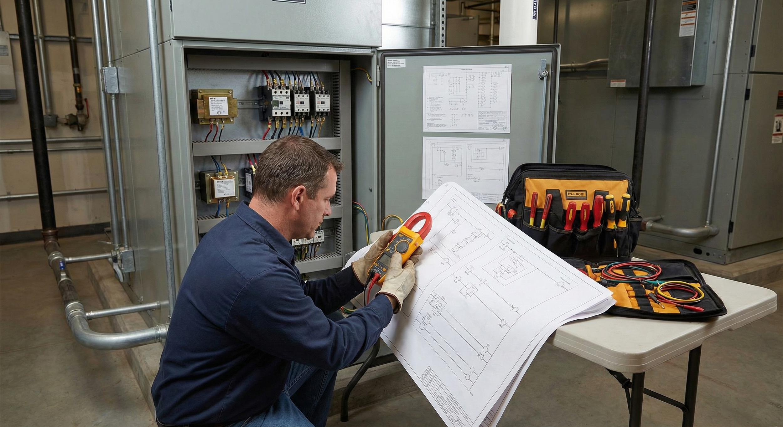
HVAC technician performing electrical troubleshooting
Phase 1: The Professional Standard (Safety & Setup)
As a technician, your safety protocols must be muscle memory. We don't just "turn it off"; we verify.
LOTO (Lockout/Tagout): If you are working in a commercial setting or out of sight of the disconnect, apply your lock and tag. It’s non-negotiable.
Verify 0V: Never trust a disconnect switch blade. Always use your meter to verify zero energy between L1-L2, L1-Ground, and L2-Ground before touching anything.
The Schematic is Your Map: Before your meter leads touch a terminal, your eyes should be on the ladder diagram. Trace the circuit mentally first. If you don't know the sequence of operation, you aren't troubleshooting; you're guessing.
Phase 2: The Diagnostic Toolkit
Leave the cheap meter at home. Accurate diagnostics require tools that tell you the whole story.
True RMS Multimeter: Essential for accurately reading non-sinusoidal waveforms found in modern variable-speed drives and ECM motors.
Amp Clamp: Vital for checking component operation under load.
Jumper Wires (Fused): A 3-amp or 5-amp fused jumper is critical for bypassing controls safely to isolate circuits without risking the board or transformer.
Megohmmeter (Megger): For checking compressor windings integrity to ground, especially after a burnout or on older units.
Phase 3: The Systematic Workflow (Follow the Power)
Effective HVAC electrical troubleshooting is a process of elimination based on the flow of electricity. Do not "hopscotch" around the unit.
Step 1: High Voltage Verification (The Source)
Measure voltage at the disconnect. Is it correct (e.g., 240V ±10%)?
Measure voltage at the line side of the contactor.
If the contactor is pulled in, measure voltage at the load side (T1 & T2).
Pro Tip: If you have 240V in but only 200V out, you have pitted contacts creating high resistance. Replace the contactor immediately.
Step 2: Low Voltage Verification (The Command)
If the high voltage is present but the unit isn't running, check the 24V control circuit.
Measure between R and C at the terminal board or transformer secondary. Do you have 24V? If not, check the breaker, the door switch, or the transformer itself.
Measure between Y and C (for cooling call) at the board. If you have 24V, the thermostat is doing its job, and the issue is downstream (safeties or the board itself).
Step 3: Isolate the Short
If the low-voltage fuse blows immediately upon a call for cool, you have a dead short.
Stop wasting fuses. Disconnect the Y wire going outside. Restore power. Does the fuse hold?
YES: The short is in the outdoor low-voltage wiring (check for weed-eater damage) or the contactor coil.
NO: The short is inside (bad board, rubbed thermostat wire in the wall, or a bad transformer). Break the circuit down component by component to find the fault.
Phase 4: Advanced Component Diagnostics
Don't just rely on a visual inspection or a simple bench test. Components behave differently under electrical and thermal load.
1. Capacitors: Testing Under Load
While an MFD bench test is a good starting point, a capacitor can test "good" cold but fail when hot.
The Load Test: With the system running, measure amps on the start wire (HERM to compressor S terminal) and voltage across the capacitor (C to HERM).
The Formula:
Capacitor Calculator
Formula: (Amps × 2652) ÷ Voltage
Note: The constant 2652 is specific to 60Hz power.
If the running result is outside the ±6% or ±10% tolerance on the label, replace it, even if it looks fine physically.
2. Contactors: The Voltage Drop Test
A visual check for ants or burns is fine, but a voltage drop test is definitive.
With the system running (contactor closed), measure voltage across each pole (L1 to T1, then L2 to T2).
A good set of contacts should read near 0V (ideally <0.1V). If you read more than 0.5V across closed contacts, that resistance is generating heat and starving the compressor of voltage. Replace it.
3. Compressors: Distinguishing the Failure
When a compressor won't start, don't assume it's dead.
Ohm it out: Measure resistance between C-R, C-S, and S-R. Ensure
Winding Rule
The resistance readings must satisfy the following formula:
Check for Ground: Use your meter on the highest ohm scale (or a megger) from each terminal to clean copper ground. Any reading other than "OL" (infinite) indicates winding insulation breakdown.
Locked Rotor vs. Mechanical Seize: If windings are good and the capacitor is new, check the LRA (Locked Rotor Amps) on the data plate. If the compressor pulls LRA and trips the breaker instantly, it is mechanically seized. If it pulls significantly less than LRA but hums and trips on thermal overload, you might be single-phasing or have a loose connection.
Phase 5: The "Phantom" Problems (Intermittent Faults)
The hardest calls are the ones that work when you arrive but fail when you leave. These require looking for "Phantom" electrical issues.
Ghost Voltage (Use Low-Z): Sometimes you will read 40V-80V on a disconnected wire. This is "ghost voltage" induced by adjacent live wires. Switch your Fieldpiece or Fluke meter to "Low-Z" (Low Impedance) mode. If the voltage drops to zero, it’s a ghost. If it holds, it’s a live short.
The Rub-Out: Check the low-voltage wire bundle where it enters the outdoor unit cabinet. Vibration often rubs the insulation raw against the copper refrigerant line or the sheet metal, causing a short that only happens when the unit vibrates.
Loose Neutrals: In the air handler, check the white neutral wire bundle. A loose neutral can cause bizarre voltage readings (like 60V on a 120V circuit) and erratic motor behavior.
Conclusion: Fix the Root Cause
The goal of this HVAC troubleshooting guide isn't just to get the unit running today; it's to ensure it's running tomorrow.
According to the Department of Energy (DOE), dirty coils and improper airflow are leading causes of increased energy consumption and premature equipment failure. If you find a failed capacitor, don't just swap it. Check the condenser coil cleanliness and fan amp draw—excess heat kills capacitors.
A true technician doesn't just change the part that broke; they find the condition that caused it to break. That is the difference between a temporary fix and a permanent repair, and it's the key to reducing callbacks.
You can watch a practical demonstration of the "under load" capacitor test here: How to check a capacitor under load. I selected this video because it perfectly demonstrates the specific formula
(Amps × 2652) ÷ Voltage = Actual μF
referenced in the blog post, reinforcing the "Load Test" concept visually.