

The Pro’s Guide: Using an HVAC Diagnostic Chart for Rapid Electrical System Troubleshooting
In the field, speed is the byproduct of a refined process. Whether you’re staring at a 50-ton rooftop unit (RTU) or a high-efficiency residential split, the difference between a "parts changer" and a Lead Tech is the ability to apply a systematic logic flow. Utilizing a professional hvac diagnostic chart isn't about needing a crutch; it’s about utilizing a high-efficiency framework to isolate electrical faults and minimize Mean Time to Repair (MTTR).
For professional technicians, electrical system troubleshooting is a race against the clock. By adhering to a rigorous diagnostic chart, you ensure that every voltage drop measurement and continuity test brings you closer to the root cause, rather than just a symptom.
Integrating the Sequence of Operations (SOO) into Your Diagnostic Flow
Every reliable hvac diagnostic chart is built on the foundation of the Sequence of Operations. Professional hvac troubleshooting begins by identifying exactly where the logical chain was broken.
Call for Service: R to Y/W/G (24V signal initiated).
Safety String Verification: All normally closed (NC) safeties—high/low-pressure switches, float switches, and thermal limits—must be proven.
Command Execution: Control board relay closure or contactor coil energization.
Load Initiation: Inducer motors, compressors, and blower motors pulling rated FLA/RLA.
If you have 24V at the contactor coil but the unit fails to engage, the chart directs you to check for an open coil or a mechanical bind—eliminating the need to backtrack to the thermostat or control board.
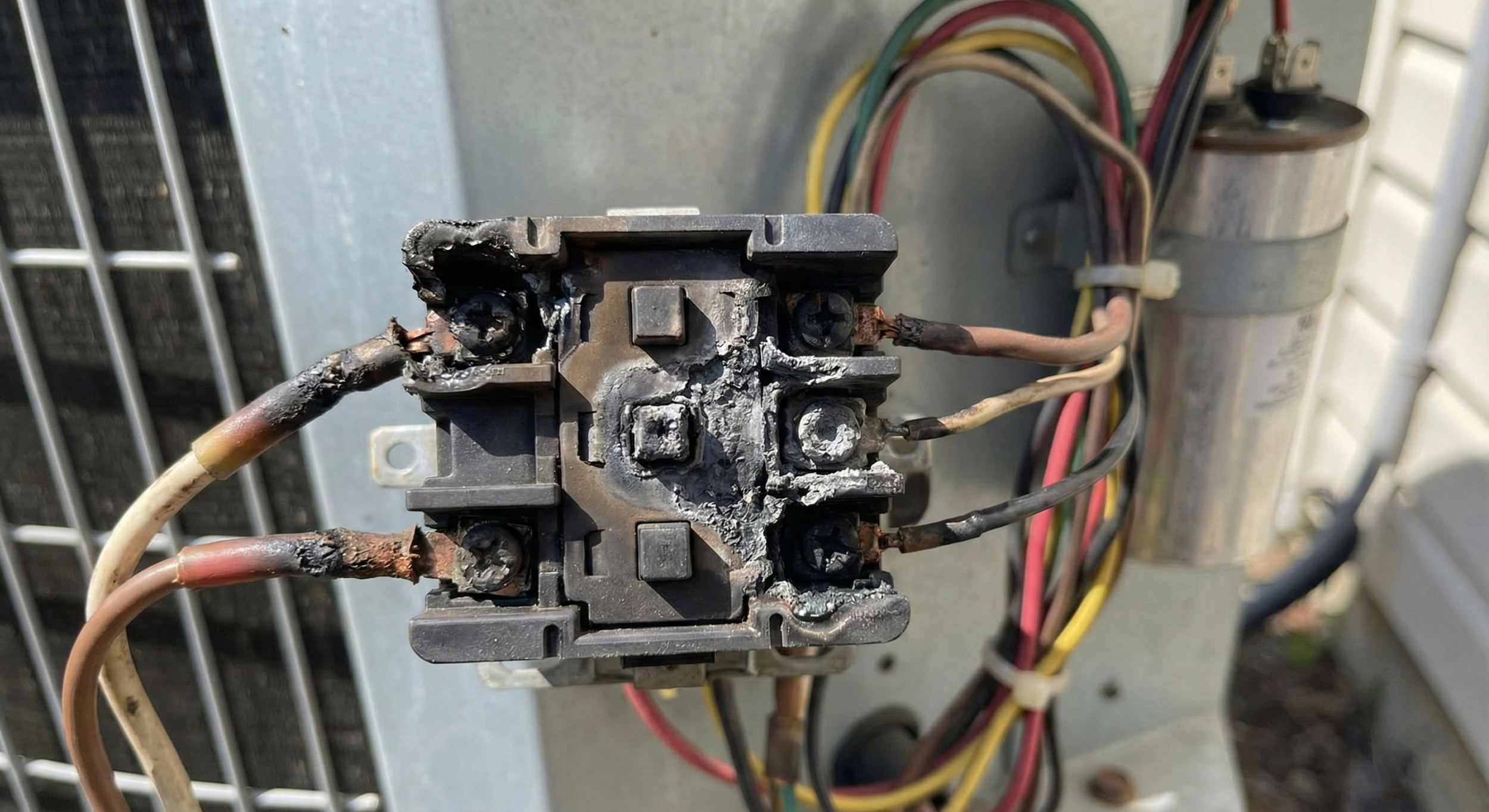
Burnt contactor found while performing electrical troubleshooting
Advanced Electrical System Troubleshooting: Professional Checkpoints
While a homeowner looks for a tripped breaker, a pro looks for high-resistance connections and under-load performance. When using your hvac diagnostic chart, keep these technical parameters in mind:
1. Identifying Voltage Drop at the Contactor
Don't just check for potential; check for quality. Measure the voltage drop across the contactor poles while the load is running. Industry standards suggest that any drop exceeding 3% to 5% of the applied voltage indicates high-resistance contacts (pitting or carbon buildup). This is a "proactive find" that prevents an emergency compressor failure down the road.
2. Capacitor Health: Beyond Microfarads
Standard hvac troubleshooting involves checking microfarads. However, a technician should verify the capacitor under load. By measuring the start winding amps and the voltage across the capacitor, you can calculate the actual capacitance while the motor is at operating temperature—a far more accurate metric for intermittent "humming" issues.
3. Troubleshooting the Safety String Logic
In commercial electrical system troubleshooting, the safety string can be extensive. Use the "Divide and Conquer" method:
Check for 24V at the end of the string (usually at the board or contactor).
If voltage is missing, move to the midpoint of the string.
By "splitting the circuit," you can isolate a tripped high-pressure switch or a clogged condensate float in half the time.
Professional HVAC Troubleshooting Logic Table
| Symptom | Logic Path | Root Cause Analysis |
|---|---|---|
| Board "Heartbeat" but No Start | Check 24V at terminal "C" to "Y" | Open safety switch (HPS/LPS) or broken thermostat wire. |
| Compressor Hums / LRA Peak | Check Capacitor & Start Kit | Weak/failed capacitor or mechanical "stuck" compressor. |
| Contactor "Chattering" | Check VA Load & Voltage at Coil | Low voltage supply, undersized transformer, or high-resistance wire. |
| VFD / Inverter Error Code | Cross-reference OEM Chart | DC Bus overvoltage or IPM module failure. |
| Fan Runs, No Compressor | Check Contactor Output Voltage | Pitted contactor points or open internal compressor overload. |
Minimizing Callbacks with Diagnostic Rigor
The most common reason for a callback is fixing the effect rather than the cause. A dedicated hvac diagnostic chart ensures you didn't just replace the blown fuse, but found the chafed wire rubbing against the liquid line that caused the short.
Pro Tip for Commercial Techs: On 3-phase systems, always check for voltage imbalance. Per NEMA standards, a voltage imbalance of just 1% can lead to a significant increase in motor winding temperature. If you find an imbalance over 2%, you must investigate the building's power distribution or the utility's supply before the motor suffers a winding failure.
Summary: Efficiency Through Data
Mastering the hvac diagnostic chart allows you to provide a more professional level of service. Instead of telling a client "the board is bad," you can confidently state: "The sequence of operations reached the control board output, but we have 0V at the terminal despite a closed relay, confirming an internal board failure."