

From Parts Changer to Diagnostician: The Advanced Electrical Troubleshooting Mindset
There is a plague in the HVAC industry: The Parts Changer.
We’ve all seen it. A technician arrives at a no-cool call, sees a swollen capacitor, swaps it, and leaves. Two days later, the compressor grounds out because the capacitor was just a symptom of a much larger heat issue.
You have already read our Technician’s Guide to Electrical Troubleshooting and mastered the Hopscotching Method. Now, it is time to master the most important tool in your bag: Your logic.
This guide isn’t about how to use a multimeter; it’s about how to think like a master diagnostician.
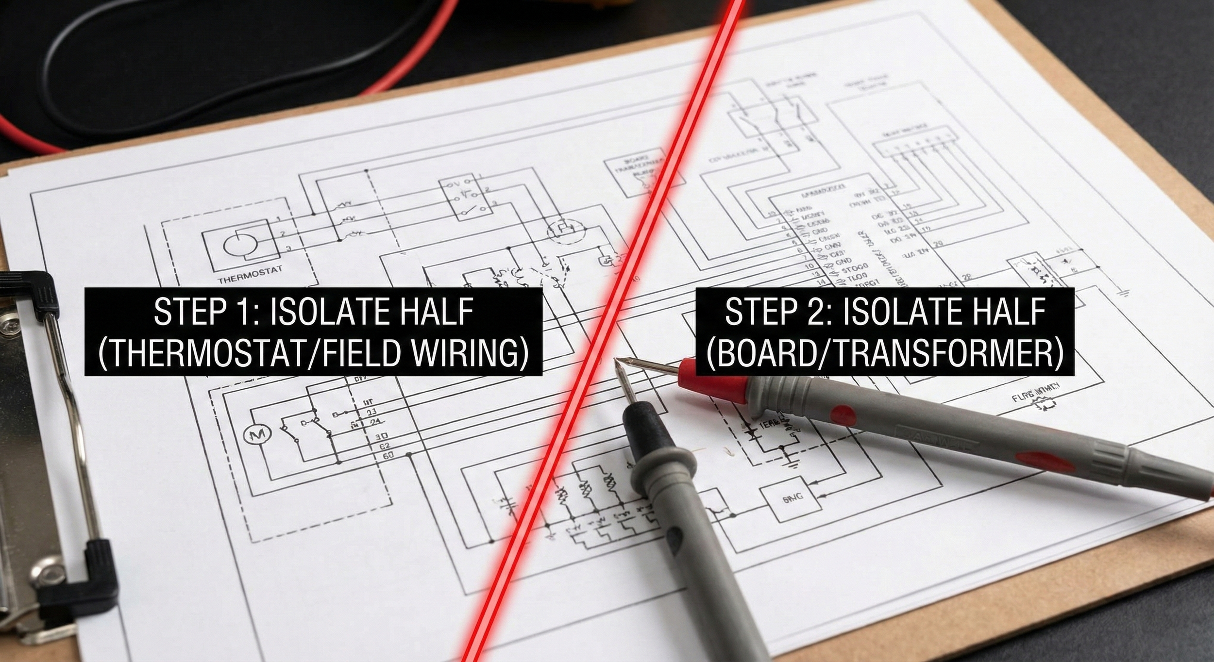
HVAC schematic demonstrating the "Divide and Conquer" electrical troubleshooting technique to isolate faults.
1. The Trap of "Confirmation Bias"
The biggest enemy of electrical troubleshooting isn't a complex schematic; it’s your own brain. When you arrive at a call and see a burnt wire, your brain wants to stop looking. You think, "I found it."
The Pro Mindset: Finding the failed component is only Step 1. If you find a burnt wire on a compressor terminal, you haven't found the problem—you’ve found the result.
The Amateur asks: "What is broken?"
The Pro asks: "What caused the heat that burned this wire?" (Was it a loose spade? High amperage? Pitted contactor points?)
Rule #1: Never repair a catastrophic electrical failure without identifying the condition that caused it.
2. Testing "Potential" vs. Testing "Load"
A common mistake during training is trusting a voltage reading on an open circuit.
Imagine a garden hose with a kink in it. If you put a pressure gauge behind the kink with the nozzle closed, it reads full pressure (Static Pressure). But the moment you open the nozzle (put the circuit under load), the pressure drops to zero.
Electricity behaves the same way.
The Mistake: Measuring 24V at a contactor coil with the wire disconnected. It reads 24V, so you assume the board is good.
The Reality: The board might have a high resistance relay. It can pass voltage, but it cannot pass current.
The Fix: Always test voltage across the load while the component is trying to fire. If the voltage vanishes when the load is connected, your problem is upstream (bad connection, bad board relay, or loose neutral).
3. The "Min/Max" Method for Intermittent Faults
The hardest calls are the ones that work perfectly while you are standing there but fail ten minutes after you drive away. These are usually electrical, and they usually involve "Ghost Failures" caused by vibration or thermal expansion.
You cannot stare at a multimeter for 45 minutes waiting for a glitch. You need to use the Min/Max function on your meter.
Hook up your leads to the control voltage leaving the pressure switch or limit.
Set your meter to Min/Max. This captures the highest and lowest voltage recorded over time.
Run the system. Wiggle wires, tap on the unit cabinet, and simulate vibration.
Review the Log. If your "Min" dropped to 0V even for a millisecond, you have a loose connection or a chattering switch that is tripping the board’s logic.
4. Root Cause Analysis (RCA) Matrix
To graduate from a parts changer to a top-tier technician, you must map every electrical failure to a root cause. This prevents the "Callback Loop."
| Electrical Failure | Lazy Diagnosis (The Parts Changer) | Root Cause Diagnosis (The Pro) |
|---|---|---|
| Swollen Capacitor | "Bad Capacitor." (Swaps and leaves) | Overheating: Check condenser coil cleanliness, fan blade positioning, and bearing friction. Heat kills capacitors. |
| Pitted Contactor | "Old Contactor." (Swaps and leaves) | Chattering/Arcing: Check for low voltage drop (21V-23V) at the coil, loose thermostat wire, or ants in the contactor. |
| Blower Motor Failure | "Bad Motor." (Swaps and leaves) | High Static Pressure: Check duct sizing and filter restrictions. High static kills ECM modules; low static kills PSC motors. |
| Repeated Fuse Blown | "Short Circuit." (Puts in bigger fuse) | Low Voltage Short: Isolate the Y-wire to the outdoor unit (often weed-eater damage) or check contactor coil resistance. |
5. The "Binary" Approach to Schematics
Stop looking at the whole wiring diagram at once, it’s overwhelming. A professional breaks the schematic into a binary "Yes/No" tree.
The "Divide and Conquer" Technique: If you have a 24V short, do not check every component. Split the system in half.
Disconnect the thermostat wires at the board. Does the fuse blow?
Yes: The short is in the board or transformer.
No: The short is in the field wiring or thermostat.
Reconnect one wire at a time (R, then W, then Y, then G).
When the fuse blows (or your resettable breaker trips), you have identified the specific branch causing the failure.
Conclusion: Invest in Your Logic
Tools like the Megohmmeter and the True RMS meter are vital, but they are useless without the logic to interpret what they are saying.
If you are ready to stop guessing and start knowing, you need to dive deeper into the physics of the trade. Review our guide on Identifying Faulty Wiring to see what physical degradation looks like, and ensure you are calculating your Capacitor and Compressor Math correctly every single time.
Master the mindset, and the repairs will follow.